ZYNQ随笔——AXI_GPIO裸机设计
时间:2019-08-07 12:07:00
收藏:0
阅读:421
1. 硬件平台搭建
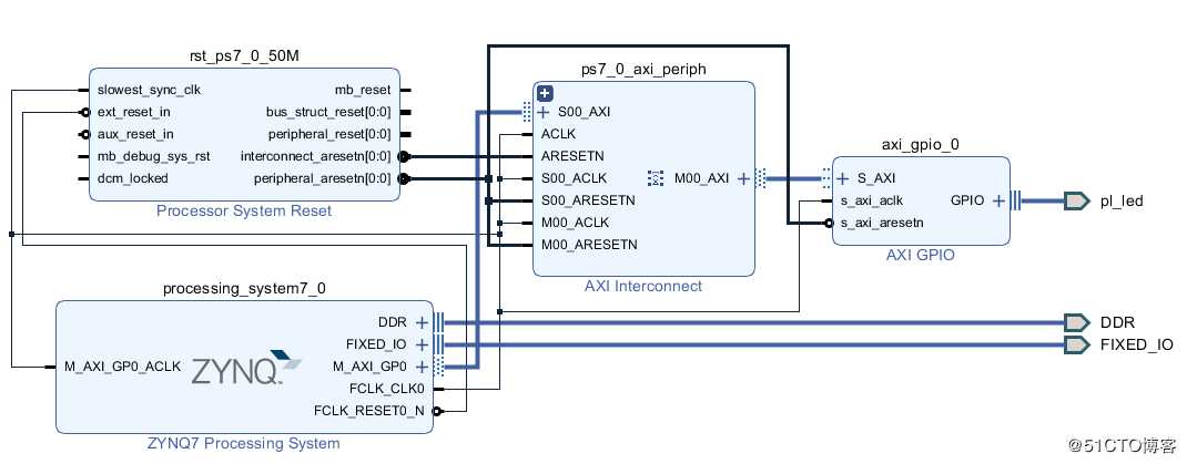
在Block Design里添加ZYNQ7 Processing System和AXI_GPIO模块,双击AXI_GPIO设置为输出,驱动外部IO器件(如LED)。搭建好的系统结构如下图所示:
2. 软件SDK设计
SDK软件设计可以参考官方设计文档,主要API函数有,
在Block Design里添加ZYNQ7 Processing System和AXI_GPIO模块,双击AXI_GPIO设置为输出,驱动外部IO器件(如LED)。搭建好的系统结构如下图所示:
2. 软件SDK设计
SDK软件设计可以参考官方设计文档,主要API函数有,
- int XGpio_Initialize(XGpio * InstancePtr,u16 DeviceId)
- void XGpio_SetDataDirection(XGpio * InstancePtr,unsigned Channel,u32 DirectionMask)
- void XGpio_DiscreteWrite(XGpio * InstancePtr,unsigned Channel,u32 Data)
- u32 XGpio_DiscreteRead(XGpio * InstancePtr,unsigned Channel)
- void XGpio_DiscreteClear(XGpio * InstancePtr,unsigned Channel,u32 Mask)
具体代码如下,
int main(void)
{
    int Status;
    volatile int Delay;

    /* Initialize the GPIO driver */
    Status = XGpio_Initialize(&Gpio, GPIO_EXAMPLE_DEVICE_ID);
    if (Status != XST_SUCCESS) {
        xil_printf("Gpio Initialization Failed\r\n");
        return XST_FAILURE;
    }

    /* Set the direction for all signals as inputs except the LED output */
    XGpio_SetDataDirection(&Gpio, LED_CHANNEL, ~LED);

    xil_printf("Gpio Example\r\n");

    /* Loop forever blinking the LED */

    while (1) {
        /* Set the LED to High */
        XGpio_DiscreteWrite(&Gpio, LED_CHANNEL, LED);

        /* Wait a small amount of time so the LED is visible */
        for (Delay = 0; Delay < LED_DELAY; Delay++);

        /* Clear the LED bit */
        XGpio_DiscreteClear(&Gpio, LED_CHANNEL, LED);

        /* Wait a small amount of time so the LED is visible */
        for (Delay = 0; Delay < LED_DELAY; Delay++);
    }

    xil_printf("Successfully ran Gpio Example\r\n");
    return XST_SUCCESS;
}
3. 编译运行
下载FPGA代码,以Hardware运行软件后,在终端打印了GPIO Example,外部LED不停闪烁。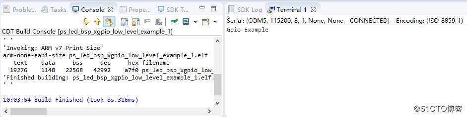
原文:https://blog.51cto.com/shugenyin/2427320
评论(0)